HOME / BLOG / PDU + BBU + PSU INTEGRATION
INTEGRATION · SEP 16, 2026
Integrating PDU, BBU and CRPS PSU in One Rack
Rack power does not fail because a PDU is badly made or a power supply misses its efficiency target. It fails at the interfaces — protocol maps that do not match, hot-swap behaviour nobody tested, a bus voltage nobody verified under a real load step. This is the integration work, written as a sequence you can commission against.
THE INTERFACE MAP
Seven interfaces decide whether the rack works.
Before anything is ordered, the integration is a list of hand-offs. Each row below is a place where two devices must agree on something that neither datasheet fully specifies — and therefore a place to fix in the pilot, not in the hall.
| Interface | Between | What has to be agreed |
|---|---|---|
| AC input | Busway tap-off or PDU inlet to the 3φ feed | Phase rotation, inlet connector family, cord length, feed rating against the 63A class |
| Outlet to shelf | PDU outlets to CRPS shelf AC inputs | C13/C19 map, per-shelf diversity across A and B sides, branch circuit assignment |
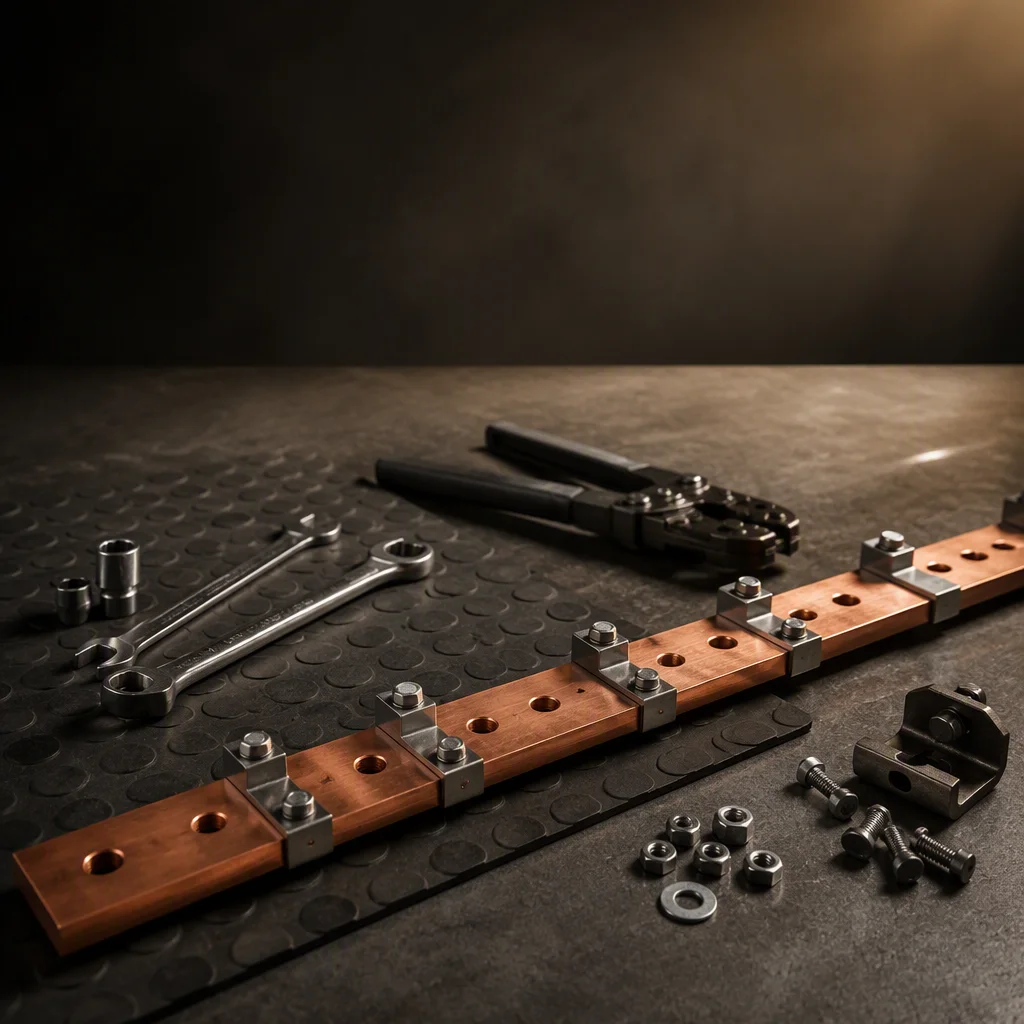
| DC bus | Shelf output to rack busbar, BBU and supercapacitor banks | Bus voltage naming and tolerance, terminal torque, per-module disconnect, hot-swap behaviour |
| PSU telemetry | Modules to shelf manager over PMBus | Register map, alarm severity levels, polling interval, firmware revision |
| BMS telemetry | BBU packs to shelf manager or rack controller | CAN frame layout or RS485 Modbus register map, SoC/SoH reporting, cell temperature units |
| Rack telemetry | PDU to DCIM | SNMPv3, Modbus TCP or Redfish profile, outlet naming convention, metering resolution |
| Mechanical and thermal | All three devices in one enclosure | 0U versus 1U mounting, RU shelf height, front-to-back airflow direction, cold-plate option |
ORv3 ALIGNMENT
What ORv3 alignment buys — and what it does not.
Standard mechanics, standard bay, standard bus
OCP ORv3 alignment is why a rack BBU and a CRPS power shelf can share an envelope: a defined 48V rack busbar, RU-form hot-swap shelves with per-module disconnect, front-to-back airflow and management conventions that assume telemetry is polled rather than read off a display. For a buyer it means modules from more than one vendor fit the same bay, and a BMS that speaks the manager's language does not need a custom gateway to do it.
It stops at the rack boundary
ORv3 says nothing about the AC PDU upstream, the busway tap that feeds it, or the DCIM that consumes the data. Those remain the integrator's problem — which is precisely where multi-vendor racks come apart. On the DC side of the shelf, alignment gives you a mechanical and electrical contract. On the AC side, someone still has to own the metering chain, the phase balance and the breaker coordination, and "someone" needs a name in the purchase order.
A note on 48V versus 54V naming
The rack bus is a nominal 48V in OCP ORv3 language and a 54V rail in AI shelf datasheets — the same conductor described by two conventions, one from the open-compute side and one from the vendor side. When you write the integration spec, fix one naming and one tolerance for the bus and use it in every document: the alternative is a commissioning argument about whether a reading is in tolerance. Our own lines are quoted as an ORv3 48V busbar for the BBU and a 54V output for the shelves, and the two land on the same node.
TELEMETRY AGGREGATION
Four protocols, one dashboard.
Aggregation is a data-modelling problem wearing a networking costume. Collecting the points is the easy part; making them agree on identity, time and severity is what makes a rack visible.
| Source | Protocol | Points that matter | Where it lands |
|---|---|---|---|
| Rack PDU | SNMPv3, Modbus TCP, IPMI, Redfish | Per-outlet current at ±1%, inlet totals, phase currents, switch state, environment sensors | DCIM directly |
| CRPS modules | PMBus to shelf manager | Output current and voltage per module, input power, temperature, fan duty, fault flags | Shelf manager, then DCIM |
| BBU packs | CAN or RS485 Modbus | State of charge, state of health, cell temperatures, per-pack current, contactor state | Shelf manager or rack controller |
| Supercapacitor bank | Module telemetry option | Bank voltage, per-cell over-voltage events, module temperature | Rack controller |
| Busway tap | Per-tap metering, Modbus | Current at the point of change — the upstream check on everything below it | DCIM |
Fix identity, time and severity first
Three conventions make an aggregation project succeed or stall. Identity: every point named by row, rack, position and function, matching the rack elevation rather than the device's own default string. Time: one time base across PDU, manager and controller, so a bridging event can be read as a sequence instead of three unsynchronised logs. Severity: agreed alarm classes, because a warning on one vendor's device is often another's critical, and a dashboard that cries wolf gets ignored.
Redundancy shows up in the data, not the spec sheet
N+N hot-swap is a claim until the telemetry proves it: pull one module under load and the output current of the remaining modules should step up while the bus stays inside tolerance, with the event captured at both the shelf and the PDU. That single test is worth more than any redundancy diagram, because it exercises the control loop, the load sharing and the reporting path at the same time.
COMMISSIONING SEQUENCE
Eight steps, in this order.
Commissioning runs from the upstream boundary towards the silicon, so that every layer is proven before the layer below it is energised. Reordering these steps is how a rack ends up with two variables changing at once.
Feed verification
Confirm the tap rating, phase rotation and voltage at the point of connection against the single-line, with the rack isolated.
PDU bring-up
Energise the PDU, verify firmware and outlet map, and check its metering against a calibrated reference — the ±1% billing-grade claim is a test, not a label.
Phase balance check
Measure per-phase current with a known load distribution and confirm the balance predicted by the outlet map.
Shelf power-up
Bring up the CRPS shelf, confirm N+N module population, then pull one module under load and record load sharing and bus tolerance.
Bus verification
Check busbar voltage at the far end under load, torque terminals to spec, and confirm per-module disconnect behaviour.
BBU commissioning
Map BMS telemetry, set the SoC window to the dispatch policy, then capture a bridging event under a real load step rather than a bench resistor.
Capacitor layer
Verify the supercapacitor bank responds in the millisecond window and that per-cell protection reports into the same telemetry path.
Alarm walk and handover
Force every alarm class, confirm DCIM receives it with the right severity, then hand over one test record keyed to one serial range.
PROVING THE BUFFER
What a load-step capture should show.
The test that matters most
GPU load can step by tens of kilowatts in under a second while the facility chain — transfer switch, generator — answers on a 1–90 minute clock. The buffer layers exist to span that mismatch, and the only way to know they do is to step the load and watch the bus. Record bus voltage before, during and after the step; the time the supercapacitor bank and then the BBU take over; the state of charge before and after; the recovery time to nominal; and confirmation that no IT load dropped.
Bench tests do not count
A BBU discharged into a resistive bank proves the battery works. It does not prove the control loop that decides when the battery takes over, nor the telemetry that reports it, nor the interaction with the shelf's own regulation. Cold-plate compatibility, per-pack BMS limits and the SoC window your dispatch policy assumes only show up under a real step. Run it at pilot on the factory floor as a system, and the hall commissioning becomes verification of a known result instead of a first attempt.
FAILURE MODES
Where integrated racks actually break.
These are the seams. Every one of them is invisible on a datasheet and obvious in a commissioning log.
| Failure mode | Root cause at the interface | Design answer |
|---|---|---|
| Shelf manager cannot poll the PDU | Firmware profile or protocol revision mismatch between two vendors | Protocol profile and firmware revisions fixed during the pilot, verified on the pilot rack |
| BBU telemetry ignored by the manager | CAN frame layout or register map differs from the assumed one | BMS map configured per program; SoC and cell temperature points verified end to end |
| Nuisance trip on a load step | Breaker and metering coordination never checked against the real step profile | Step-test capture compared against the protection settings before handover |
| Hot-swap event takes the shelf down | Inrush or pre-charge behaviour untested on the actual bus | Module pull-and-replace under load as a standard commissioning step |
| Dashboard timelines do not line up | PDU, manager and controller on different clocks | One time base for the rack, agreed at configuration time |
| Redundancy that is not redundant | A and B sides sharing a common feed, tap or breaker | Diversity verified on the single-line and then measured at the outlet |
One serial range, one record
The commercial version of this brief is simple: when one factory owns the PDU, the shelf, the battery and the capacitor bank, every one of those seams is an internal hand-off that gets tested before the crate closes. A pilot integrated rack leaves with busway tap temperature-rise data, PDU metering accuracy against reference, PSU burn-in logs and a bridging capture under real load steps — one serial range, one QA file, one call when something needs an answer.
RELATED SYSTEMS
The hardware behind this brief.
Rack PDU
Five tiers, 16–63A, 3φ past 22 kW+, ±1% billing-grade metering and SNMPv3 / Modbus TCP / IPMI / Redfish telemetry.
Explore rack PDUs →BBU Battery Backup
51.2V LFP on the ORv3 48V busbar, 3–6 kWh per shelf typical, N+N module groups, CAN or RS485 BMS telemetry.
Explore BBU →Integrated Rack Power
Busway, PDU, PSU and buffering engineered as one system — joint commissioning and one QA file up to 142 kW per rack.
Explore integration →
INTEGRATION PROGRAM